OpenBuildings™ Designer Help

IFC Export

Used to export the building model to an IFC file.

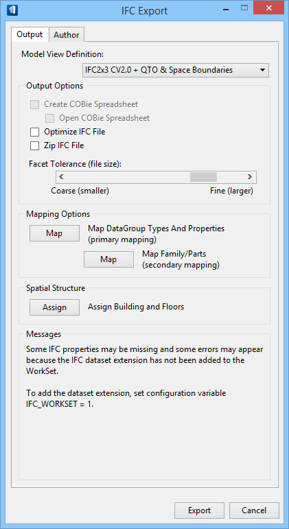
The active DGN file and all displayed References are exported using information and settings specified (Output tab). Author information can also be entered (Author tab) to be exported with the model.

Accessed from:
  • Backstage: File > Export > Exchange File Type > IFC (*.IFC)


SettingDescription
Model View Definition Sets the model view definition schema used to export the IFC file.
IFC2x3 Schema - IFC is a data schema which describe and exchange construction and facilities management information. It provides logical order of entities (Spatial and Physical components)
  • IfcProject - Information which needs to be exchanged.
  • IfcSite - represents project site. [ For OpenBuildings Designer it is Floor Manager Site]
  • IfcBuilding - Buildings / OR Buildings. [For OpenBuildings Designer Building defined in Floor Manager]
  • IfcBuildingStorey - represents building floors. [For OpenBuildings Designer Floors in Floor Manager]
  • IfcSpace - Collection of spaces includes in Building Storey.
  • IfcBuildingElement - Identifies construction elements of a building associated with the floor. [In OBD ex. Door, Window etc]

In general, a MVD, or "Model View Definition" is a selection of classes from the overall IFC Schema. You can find general information about MVD on BuidingSmart site. Click Here.

  • IFC2x3 CV2.0 - IFC2x3 - is an IFC schema version while CV 2.0 is a MVD
    1. This schema focuses on coordinating Architectural, Structural, and MEP tasks during the design phase.
    2. This schema specifies which MVD we want to refer to and identifies classes present in that schema only.
    3. An example is a combined BIM model using Architectural, Structural, and MEP components.
  • IFC2x3 CV2.0 + QTO & Space Boundaries - In addition to IFC2x3 CV2.0 it also have the following capabilities
    1. Exports additional space boundaries. (In OpenBuildings Designer it is defined as OpenBuildings Designer spaces which are shapes defining the extent of space contact with adjacent surfaces like Walls, Slabs and Openings).
    2. Used for Building Energy Analysis and Quantity take-off.
    Note: Supports add-on views, such as BaseQuantities and SpaceBoundaries. It describes the additional IFC support required to fulfill the exchange requirements between the architectural and building service modeling software and the thermal analysis software which includes:
    • Proper export of the architectural building information model with some level of preprocessing for thermal analysis
      • Main focus hereby is the correct definition and processing of space boundaries (also called thermal boundaries)
      • Space boundaries can be defined as 1st level space boundaries, or 2nd level space boundaries
    • Other requirements for spaces, zones, and thermal properties of building elements.
    Note: The selected definition also provides Quantity Take-Off for cost estimation and calculation processes across the boundaries of proprietary software solutions and brings in project teams to collaborate while using CAD and cost estimation / calculation software tools of their choice. The Quantity Take-off add-on view -adds the ability to transmit base quantities for all spatial, building, building service and structural elements.
  • IFC2x3 Facilities Management Handover -This MVD defines the basic view providing data for facility management
    1. It handover model information to CAFM (Computer Aided Facility Management )and CMMS (Computerized maintenance management system)
    2. The scope of this view is to summarize the list of spaces and equipment for spatial object systems.
    3. IN addition to above CV it helps in the following
      • i. Assign furnishings to rooms.
      • ii. Group rooms to zones.
      • iii. Assign classification to spaces and components.
      • iv. Assign manufacturing properties to the components.
      • v. Exports basic quantities for all project components and its spatial structure.
      • vi. Example is COBie , which is a specification used to provide information on facility management. COBie is a spreadsheet data format to provide a subset of BIM and not geometric model information.

IFC4 Schema - It includes new classes to provide further information and two new MVDs (Reference View and Design Transfer View) for more specific view definitions and supports the purpose of IFC data exchange.

  • IFC4 Reference View
    • View that represents simplified model geometries and relationships .
    • This view is used for coordination between various project disciplines (Architectural , Structural and MEP OR Plant)
    • This MVD has rich building data content .
    • Support workflow based on reference models.
    • Subset of IFC4 DTV.
  • IFC4 Design Transfer View [Technology Preview]
    • Advanced representation of geometries and relationships of construction elements and environments in more detail than the Reference View.
    • Enables a model with great detail of information that is transferable from one software to another (One-way ) with higher data accuracy.
    • Ownership is handed over to the receiver.
    • Superset of IFC4 RV.
  • IFC4 DTV with NURBs [Technology Preview] - This MVD support exchange of rich geometry parameters like advanced B-Rep [NURBS) , Faceted B-Rep
    • Advanced B-Rep (boundary representation model in which all faces, edges and vertices are explicitly represented)
    • In the IFC4 schema, it is possible to generate B-rep objects as advanced B-reps using NURBS (non-uniform rational B-splines) surfaces. The bodies are represented more accurately.
Create COBie Spreadsheet Enabled when the Facilities Management Handover Model View Definition is selected.
A COBie spreadsheet is created upon export, when on.
  • Open COBie Spreadsheet – Enabled when the Create COBie Spreadsheet is on. The COBie spreadsheet is opened upon export, when on.
Optimize IFC File The IFC file is optimized and reduced in size, when on. The file can further be optimized and reduced in size using the Bentley IFC Optimization utility .
Zip IFC File The exported IFC file is compressed and stored in the selected output folder with the file extension *.ZIP, when on.
Facet Tolerance (file size) Controls the facet tolerance of curved surfaces. Facets that are more coarse reduce the file size. Coarser facets reduce the file size; finer facets increase the file size.

When Facet Tolerance (file size) is controlled by the configuration variable IFC_FACET_TOLERANCE, the slider control is disabled. A flyover hint explains the reason.

Map DataGroup Types and Properties (primary mapping) Opens the Map DataGroup Types and Properties to IFC dialog where datagroup types and properties are mapped by class and property to the IFC Export file.
Map Family/Parts (secondary mapping) Opens the Map Custom BuildingDesigner Dataset to IFC Dataset dialog where part and family properties are mapped to IFC entities.
Assign Building and Floors Opens the Assign Models to Spatial Containment dialog where a site/building and floor can be assigned to each model in the active project before the active DGN file is exported.
Messages Important messages are displayed here including information regarding IFC2x3 properties and the project workset.

Author tab


SettingDescription
IFC Author
  • First Name – Used to enter the first name of the author that exported the IFC file.
  • Last Name – Used to enter the last name of the author that exported the IFC file.
  • Role – Used to select the role/position of the author that exported the IFC file.
  • E-Mail – Used to enter the e-mail of the author that exported the IFC file.
  • Phone – Used to enter a phone number for the author that exported the IFC file.
Organization
  • Name – Used to enter the organization name for the author that exported the IFC file.
  • Country – Used to enter the name of the country where the organization, for the author that exported the IFC file, is located.
  • Postal Code – Used to enter the postal code where the organization, for the author that exported the IFC file, is located.
  • City – Used to enter the city where the organization, for the author that exported the IFC file, is located.
  • State – Used to enter the state where the organization, for the author that exported the IFC file, is located.
  • Address – Used to enter the postal address where the organization, for the author that exported the IFC file, is located. Two address fields are available to enable completeness of address information.
Comment This text box is available to enter any other required, supplementary, or miscellaneous information and comments.

Dialog Controls

SettingDescription
Export Opens a save as dialog (IFC File for Export dialog) with the save as file type filter set to *.ifc. The default save in folder is defined by TFDIR_IFC, and the file name defaults to the name of the active DGN file. Both can be changed. If a file with the same name already exists in the save in folder, the Confirm Save As message box opens with prompts to replace it.
Note: If the Create COBie Spreadsheet is enabled, the COBie Spreadsheet for Export dialog opens in addition to the IFC File for Export dialog with its file type filter set to *.xlsx
Clicking Save in either save as dialog starts the IFC Export process. A progress bar opens to report the export process.

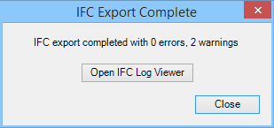
Upon completion, the progress bar and IFC Export dialog close. A message displays in the Message Center to report that the IFC Export is finished, and the IFC Export Complete dialog opens.


Clicking Open IFC Log Viewer opens the IFC Log Viewer utility where you can view log file details.
Note: The IFC Log Viewer can also be opened from (File > Utilities > IFC Utilities > IFC Log Viewer Utility) to view logs offline.
Cancel Cancels the IFC Export operation and closes the IFC Export dialog.
Key-in: IFCOUT [ FILENAME ] [ OPTIONS ]
Note: This tool is enabled only when the MDL application TFIFC is loaded. Selecting the backstage tool (via File menu) automatically loads the application. Because TFIFC is not loaded by default when starting OpenBuildings Designer, the key-in listed for this tool will not respond if keyed in before using the tool selection.
Tip: See also: Using the Key-in IFCOUT .